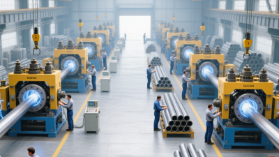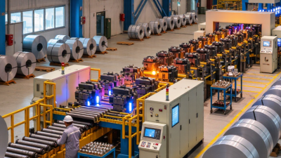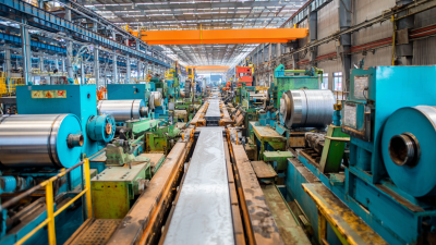
Choosing a welding machine for a tube mill is a production decision, not a catalog exercise. The right system must match tube diameter, wall thickness, steel grade, line speed, and expected shift patterns. A mismatch can show up as unstable welds, excessive trimming, or a line that cannot maintain its target pace. Small details matter.
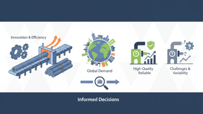
The World Steel Association’s October 2024 Short Range Outlook forecast global steel demand at 1,751 million tonnes for 2024 and 1,772 million tonnes for 2025. That forecast does not measure tube-mill output, but it highlights the scale of the steel supply chain that tube producers serve. For buyers evaluating a Pipe Welding Machine Tube Mill Production Line, the practical questions are more specific: Does the machine provide stable power at the required speed? Can operators monitor weld quality and adjust settings consistently? Are tooling, cooling, and maintenance support suited to the planned operating schedule? Not speed alone.
A credible comparison should use the mill’s actual product range and trial data, rather than headline power ratings. Ask suppliers to document weld performance on representative material and explain how they support commissioning and routine maintenance. I cannot responsibly attribute a direct quotation to a named industry expert without a verifiable source. A sourced quotation should be added only after its wording and attribution are confirmed. That caution is deliberate: purchasing advice is useful only when its evidence can be checked.
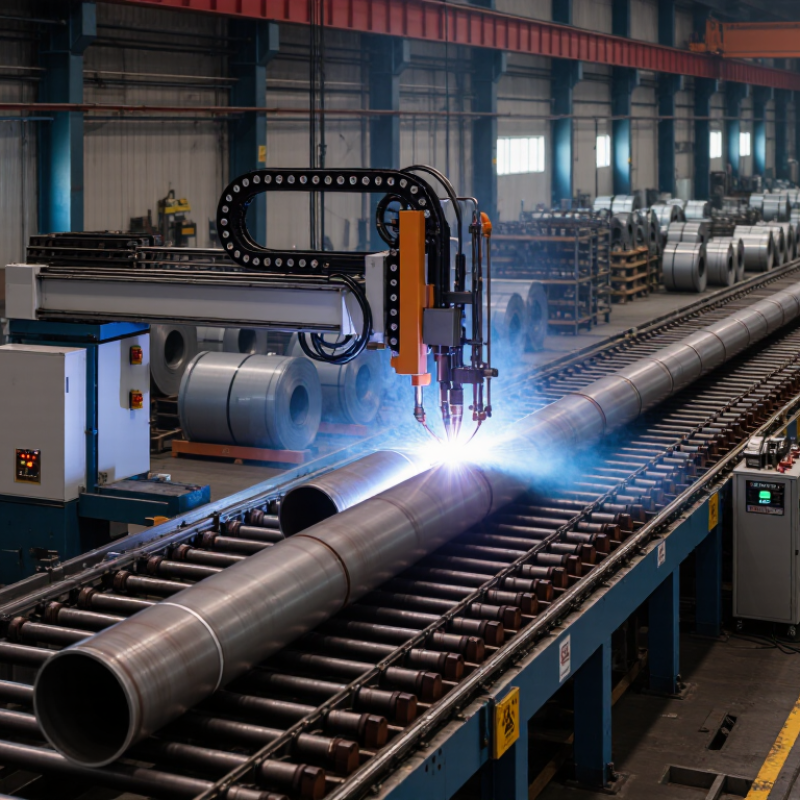
How to Choose a Pipe Welding Machine for a Tube Mill Line?
Map the full tube range before comparing machine ratings. Record minimum and maximum outside diameter, wall thickness, and planned line speed. A machine that suits one sample size may struggle across the production range. Wall thickness affects heat demand; diameter influences forming and weld-zone geometry. At higher speeds, the welding system must deliver enough energy consistently, not just reach a headline output.
Steel grade changes the welding window. ISO 3183:2019 specifies minimum yield strengths of 245 MPa for L245 and 360 MPa for L360. ASTM A500/A500M lists 315 MPa for Grade B and 345 MPa for Grade C. These figures help identify material differences, but yield strength alone cannot set welder power. Check the actual chemistry, surface condition, and supplier’s material data. Small changes matter.
Match the machine’s usable power and control range to the thickest, fastest, hardest-to-weld combination you expect to run. Then verify it with trial welds, destructive testing, and a stable production run. Log edge temperature, weld appearance, and speed during trials. A catalog maximum is not a reliable production target. I would leave room for variation, though the exact margin needs validation on your own line.
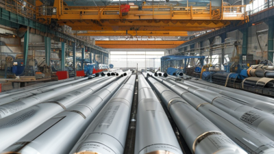
Map tube outside diameter (OD), wall thickness, steel grade, and target line speed. The chart shows illustrative HF-ERW planning scenarios; actual achievable speed depends on mill design, weld quality requirements, tooling, and process settings.
Planning examples: 25.4 mm OD × 1.0 mm wall, low-carbon steel — 90 m/min; 50.8 × 2.0 mm, low-carbon steel — 60 m/min; 76.2 × 3.0 mm, HSLA steel — 35 m/min; 114.3 × 4.0 mm, HSLA steel — 20 m/min. These are example targets, not guaranteed machine ratings. Confirm the operating window with the machine supplier using your material grade and product range.
Choose an HF generator frequency around the weld, not just from a catalog. In tube mill lines, 100–400 kHz is common. It is a working range, not a universal setting. Smaller, thin-wall tubes may perform well at higher frequencies, while larger sections can require different conditions. Wall thickness alone is not enough to choose.
Frequency affects how current concentrates along the strip edges and how quickly heat builds. A poor match can contribute to cold seams, excessive edge upset, or an unstable weld. Check the vee angle, line speed, material grade, and impeder condition too. Small changes matter. Even a slight coil-position shift can affect heating.
Ask for a frequency range based on your tube dimensions and target speed, then verify it with trial welds and appropriate seam testing. Record power, current, voltage, and weld results for each run. Do not chase a tidy number on the display. A setting can look convincing while the seam tells another story. Review setup variation and worn components before blaming frequency.
Choosing a pipe welding machine starts with the actual tube specification, not a catalog power figure. Steel, stainless steel, and other conductive materials respond differently to high-frequency heating. Record the material grade, outside diameter, wall thickness, and target line speed. Small changes matter. A thicker wall usually needs more energy, while higher speed reduces the time available to heat the weld edges.
Size the power supply for the hardest regular production condition, then check that it can run steadily at typical speeds. Too little power can leave cold welds; excessive power may overheat the edges and increase trimming or cracking risks. Ask suppliers for operating ranges and verify them with trial runs using your own material. Watch the seam color, bead shape, and weld test results. Real production is rarely as tidy as a specification sheet.
The impeder also needs to match the tube’s inside diameter and welding setup. Its ferrite core concentrates current near the seam, but poor fit, heat buildup, or misplaced positioning can reduce performance. Leave enough clearance for reliable cooling and movement through the mill. Check the impeder after setup changes, especially when switching wall thickness or tube size. A sensible starting point helps, but it is not a guarantee. Measure results, adjust cautiously, and record settings that produce consistent welds at the required speed.
When choosing a pipe welding machine for a tube mill line, check that the uncoiler, strip guides, and forming rolls can keep the coil centered. A few millimeters of lateral drift can make one edge lead the other. The strip should enter the forming section flat, without a twist or sudden side pull. Small shifts matter.
Before squeeze welding, set a consistent Vee between the strip edges. A typical included angle is about 3–7°, but the right setting depends on material, wall thickness, line speed, and the welding process. Confirm how your mill defines and measures the angle; setup references may use different points. Keep the Vee apex steady near the intended heating zone. If the angle opens or closes along the seam, check coil tracking, edge condition, and roll alignment before changing squeeze pressure. More pressure may hide the symptom, not fix its cause.
Tips: Mark the coil centerline and inspect edge tracking at startup and after a coil change. Watch for a wandering apex or uneven edge meeting. Record settings that produce a stable seam, but recheck them for each material and thickness. A good setup can still drift.
| Setup parameter | Practical starting point | What to set or verify | Why it matters |
|---|---|---|---|
| Coil position | Align the strip centerline with the forming and welding mill centerline. | Check the coil payoff, entry guides, and strip path under operating tension. Confirm the strip tracks consistently rather than drifting toward either side. | Stable tracking helps the strip edges meet evenly and reduces variation in the weld vee and finished tube. |
| Strip edge alignment | Bring both edges together with minimal mismatch; use the product drawing and mill capability to set the allowable limit. | Inspect edge position at the welding point. Check for coil camber, edge damage, and guide wear if alignment changes across the coil. | Edge mismatch can produce an uneven weld, inconsistent upset, or a seam that is off-center. |
| Vee included angle | A typical initial range for high-frequency tube welding is 3–7°. | Measure the angle between the converging strip edges near the weld point. Keep the vee symmetrical and adjust forming or guide settings in small increments. | The vee geometry affects edge heating and the conditions at which the edges meet. The suitable angle depends on material, wall thickness, speed, and tooling. |
| Vee length and apex position | Set according to the welding machine, impeder arrangement, tooling, and qualified process settings; there is no single suitable length for every line. | Confirm that the vee closes at the intended weld point and that the apex remains stable as line speed changes. | An unsuitable vee length or apex position can affect heating efficiency and weld consistency. |
| Forming rolls and guides | Use the tooling specified for the tube size and material, with guides centered and rolls in good condition. | Check roll setup, guide clearance, alignment, and wear. Verify the tube is not being forced sideways before the welding section. | Correct forming supports consistent edge presentation and helps maintain the selected vee angle. |
| Welding power and frequency | Select equipment and settings suitable for the material, wall thickness, tube diameter, and required production speed. | Use the machine manufacturer's operating range and a qualified procedure. Confirm that power delivery remains stable during production. | Power requirements vary with product and line conditions; a rating alone does not guarantee a sound weld. |
| Squeeze rolls and weld upset | Set squeeze to achieve consistent edge forging and the specified weld appearance; do not use a universal force value. | Check roll alignment, mechanical condition, and the resulting upset. Confirm weld quality through the inspection and testing plan. | Insufficient or excessive squeeze can affect the weld seam, upset, and dimensional quality. |
| Line speed | Establish speed through trials within the capacity of the welding power supply, forming section, and downstream equipment. | Record speed together with power, vee geometry, material, and inspection results when qualifying a setup. | Changing speed changes the available heating time and may require the welding setup to be requalified. |
| Cooling and impeder condition | Use the specified cooling arrangement and an impeder suited to the tube size and welding setup. | Inspect impeder position and condition, and verify coolant flow and temperature against equipment requirements. | Proper cooling and impeder setup support repeatable heating and help protect equipment. |
| Machine selection checks | Match the mill and welder to the intended tube-size range, material grades, wall thicknesses, and target output. | Review available power, frequency range, compatible tooling, cooling capacity, controls, safety features, and service support. | A suitable machine must cover the complete product and process window, not just one nominal production condition. |
| Setup note: The 3–7° vee is a typical starting range, not a universal specification. Confirm final coil position, vee geometry, power, speed, and squeeze settings through machine-specific trials and the applicable weld procedure, inspection plan, and product requirements. | |||
A pipe welding machine should be selected against the product specification, not just line speed. API Specification 5L governs line pipe, while ASTM A53/A53M covers pipe from NPS 1/8 to NPS 26, or 10.3 to 660.4 mm. That range is a useful reminder: one mill setup may not suit every diameter or wall thickness. Confirm the required grade, product specification level, seam type, and purchaser requirements before fixing the welder’s output and inspection interface.
Define NDT coverage in the purchase specification. API 5L requirements vary with product specification level and pipe type; ASTM A53/A53M also sets product-specific inspection and testing requirements. Do not assume one sampling rate satisfies both. For a longitudinal seam, specify the method, scan path, speed, and acceptance criteria. ASTM E213 covers ultrasonic testing of metal pipe and tubing, while E273 addresses weld-zone examination. Check the seam. A test record without a coverage map can leave blind areas near the weld edges or pipe ends.
During commissioning, verify probe position and calibration against the applicable reference standard, then record encoder readings and rejected sections. A short trial run can expose tracking drift before production begins. It is tempting to trust a stable display. I would still review a physical cut-up and the NDT log together; neither alone tells the whole story. Sources: API Specification 5L and ASTM A53/A53M and E213/E273.